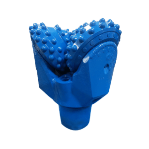
In Dubai, around a year prior, a contractor by the name of Ahmed drove a regular soil auger into the ground, expanse underlaid by the typical weathered limestone, thinking that it would suffice for the transition layer. It took less than 48 hours of normal use only to see rounded flights and polished cutting teeth. A brand new auger cost a many as $8,000 and involves two lost drilling days. If the rock auger had carbide bullet teeth, it would take at least 800 hours to work in the same formation.
Most engineering practitioners would have a similar story to Ahmad’s. The problem is not with the augers but the augment this time around. It is the selection process. A large fraction of virtues has to be ignored most of the time when it comes to the effective deployment of augers, even today. There are more decent working hours to the right augers than to the wrong ones. One for precision, the other generic. And efficacy, that’s the other matter, hours, dollars, and delay in the schedule show where the difference lies.
In this guide, you are provided with a structured methodology devised by manufacturers to help you in the selection of drills, providing the auger designs. The document has the following contents: description of the main types of augers, their performances depending on the soil type, methods of their selection so that they include table of torques and cost per pile, and economics of the drilling activity.
What Is a Drilling Auger?

A drilling auger, sometimes also referred to as a drill bit, is a corkscrew-shaped device commonly used in foundation and geotechnical drilling exercises, enabling the cutting and conveying of both earth and rock cuttings mechanically. It is made up of perforated central splices, spiral drowns, exchangeable tooth cutting edge, and a rotary drive mechanism that interacts with the rig column. In most applications, augers result in closed-loop fluid systems not being necessary in the drilling operations.
The core components define the auger’s capabilities. The stem can be solid or hollow. Solid stems are stronger and simpler. Hollow stems allow sampling and casing installation through the center tube. The flights are the helical blades that carry cuttings upward. Flight pitch, thickness, and wear protection determine how efficiently the auger moves spoil and how long it lasts. The cutting head carries the teeth that do the actual penetration work. Tooth geometry, material, and placement are matched to soil or rock hardness. The drive connection, usually a kelly box, transfers torque and crowd force from the rig.
Drilling bucket, as part of the core removal equipment, stores the drilling spoil inside a big cylinder and collects it for self-discharge. In contrast, the drilling auger typically removes the cutting and continues its operation. Consequently, these systems are known to outperform in soft grounds but are less effective in hard rock or loose saturated soils, where the borehole collapse is possible.
Types of Drilling Augers
The basic understanding of the six principal directions is already something and the job matches the tool. This involves different types of helicopter jack in respect of materials, working volumes and costs.
Continuous Flight Auger (CFA)
CFA is the dominant method for bored pile construction in soft to medium ground. A solid or hollow stem carries continuous helical flights from the cutting head to the top drive. As the auger drills, cuttings travel up the flights to the surface continuously. At depth, concrete is pumped through the hollow center or through a side grout tube as the auger is withdrawn. Reinforcement is placed immediately after.
It’s principle diameters range from 400 to 1200 mm and it can also be 30 meters in depth or more in height. It can rate between 20 to 40 meters a day running through soft clay which makes the method one of the fastest pile methods. This method works best in cohesive soils, dry sandy soils as well as in soft rock where no casing is used to support the borehole.
For detailed CFA specifications, see our CFA continuous flight auger specs guide.
Hollow Stem Auger
These augers encompass the straight flight helical characteristics with enhanced models for setting which covers the leg of the cutting edge and removes the bit from the tube. The central tube is being used for temporary casing which will help in bearing sand, soft clays, and groundwater areas. When it gets to this depth, the plug bits are removed and various sampling tools or casings can be slid through the hollow tube.
In fact, Hollowstem augers are the more popular method of drilling when geotechnical work, environmental sampling and certain foundation activities are done below the water table. In the event that hard rock is met, the hollow stem can be converted into a wireline coring without having to trip the whole rod.
Rock Auger
Rock augers are designed for formations that are abrasive and fully or at the very least partially consolidated. As such, their flitting is made stiffer, and their structure is blast-proof. Their cutting heads have bullet teeth or tungsten carbide inserts.
Flat rock augers handle weak fractured rock below 5 MPa compressive strength. Conical rock augers tackle medium to strong rock in the 15 to 60 MPa range. High-torque heavy-duty designs are built for solid bedrock and frozen ground.
The key difference from soil augers is not just tooth material. It is the entire load path. Rock augers need higher torque, slower rotation, and greater crowd force. Running a soil auger in rock is a fast way to destroy flights and waste rig time.
For the full hard-ground breakdown, read our guide to rock auger drilling techniques.
Soil Auger
Soil augers are the standard tool for soft to medium-density ground. Single-flight designs offer low rotary resistance and fast penetration in clay and sand. Double-flight designs provide better guidance and more efficient spoil removal, especially at larger diameters. Flat soil augers with double-cut configurations work well in uncased bores and mixed soil layers.
Soil augers are the most cost-effective option when ground conditions are predictable and non-abrasive. They wear faster in sand and gravel than in clay, but replacement flights and teeth are inexpensive compared to rock auger components.
For a deeper look at soft-ground techniques, see our guide to soil auger drilling methods.
Bucket Auger
Bucket augers, on the other hand, have a spinning, bucket-shaped apparatus that maneuvers into the ground, collects the debris from the drilling process, and is pulled back up after use. The operation is cyclic in this case, rather than a continuous action used in the CFA drilling.
They excel in large-diameter holes, below the water table, and in mixed ground where continuous flight conveyance is impractical. Bridge piers, wind turbine foundations, and deep caissons often use bucket augers because the bucket body stabilizes the borehole wall during each cycle.
Displacement Auger
In the context of augering, displacement comprises the generation of spoil piles or sleeves, which it does not have adhesive paste. While the auger drills, the soil is gathered and pushed externally in the direction of a cut, creating a compacted area around the immunized pile. The concrete is poured and advances the helical displacement when the auger is being extracted, same as CFA.
Displacement piles leave the least spoil possible, making them preferably burstiness-friendly in areas like contaminated lands, in cities where there are restrictions on leaving behind a lot of spoil, and in environments requiring minimal noise. They need certain ground conditions; that is, the primary compaction effect they look for is in the coherent soils.
For custom specifications and lead times, see our custom drilling auger specifications guide.
Master Comparison Table
| Auger Type | Diameter Range | Typical Depth | Best Ground | Torque Need | Production Rate | Cost Tier |
|---|---|---|---|---|---|---|
| CFA solid stem | 400–1,200mm | Up to 30m+ | Clay, dry sand, weak rock | 100–400 kNm | 20–40 m/day | Medium |
| Hollow stem | 150–400mm | Up to 50m | Loose sand, soft clay, groundwater | 50–200 kNm | 10–25 m/day | Medium-High |
| Rock auger | 400–1,500mm | Up to 25m | Weathered to hard rock | 300–800+ kNm | 3–10 m/day | High |
| Soil auger | 200–1,200mm | Up to 20m | Clay, silt, dry sand | 50–250 kNm | 15–30 m/day | Low-Medium |
| Bucket auger | 600–3,000mm | Up to 40m | Mixed ground, below water table | 200–600 kNm | 5–15 m/day | Medium |
| Displacement | 300–600mm | Up to 20m | Cohesive soils, contaminated sites | 150–350 kNm | 10–20 m/day | High |
How Auger Drilling Works in Foundation Construction

The CFA installation process is the best way to understand auger drilling in practice. It is also the most common application for drilling augers in modern foundation work.
Step 1: Positioning and alignment. The positioning of the rig has been done on the pile spot. The auger is attached to the kelly bar and then dropped, ensuring it is in contact with the ground. If this does not occur properly at this stage, it will result in a twist, which often is expensive to correct at a later stage.
Step 2: Drilling to design depth. In this stage, the drill rod is rotated by the rotating motion of the rotary head while it is pushed into the ground by thrust. Earth cuttings are delivered through the helix channels to the ground surface. The operator keeps the record of drilling torque, rise and speed and spoil type in order to confirm the consistency with engineering geology conditions.
Step 3: Concrete pumping during withdrawal. Once at depth, concrete is pumped through the hollow stem or grout tube as the auger is withdrawn at a controlled rate. The concrete pressure must exceed soil and groundwater pressure to prevent inflow or necking.
Step 4: Reinforcement placement. The reinforcement cage is inserted into the wet concrete immediately after auger withdrawal. Timing is critical. Delayed placement can result in concrete stiffening before the cage reaches full depth.
Step 5: Curing and integrity verification. The pile cures according to the concrete specification. Integrity testing with low-strain dynamic or sonic logging confirms pile quality before load testing or structural connection.
A Brazilian project manager named Maria switched her site from drilling buckets to CFA in soft alluvial clay. Pile installation time dropped from 8 minutes to 4.5 minutes per meter. Over a 400-pile package, that speed increase saved 23% on the piling contract value. The savings came from reduced rig time, fewer crew shifts, and no batch lifting cycles.
If you are looking for a supplier for Foundation Auger, please check out our article on Foundation Auger Supplier.
Need help matching your CFA configuration to your rig and soil profile? Our engineering team designs CFA systems with optimized flight pitch, grout tube placement, and cutting heads for your specific ground conditions. Request a CFA sizing consultation →
Drilling Auger vs Drilling Bucket: When to Use Each
Contractors often ask whether to run an auger or switch to a bucket. The answer depends on ground conditions, borehole stability, and production priorities.
| Factor | Drilling Auger | Drilling Bucket |
|---|---|---|
| Working method | Continuous spoil removal | Batch cutting and lifting |
| Best soil | Soft to medium clay, dry sand | Mixed ground, hard rock, saturated soils |
| Borehole stability | Lower; relies on flight walls | Higher; bucket body stabilizes wall |
| Speed in soft ground | Very fast | Moderate |
| Speed in hard ground | Slow; high wear | Faster; 30–50% more efficient |
| Below water table | Risk of collapse in loose soils | Better; acts as stabilizing shell |
| Tool wear | Flights and teeth wear continuously | Body and teeth wear; replaceable |
| Cost per meter | Lower in soft ground | Lower in hard or mixed ground |
| Spoil volume | Continuous; needs management | Batch; easier to control |
Decision Matrix by Ground Condition
| Ground Condition | Recommended Tool | Reason |
|---|---|---|
| Soft clay, dry sand, gravel | Auger (CFA or soil) | High speed, continuous removal, low wear |
| Cohesive soils, stable walls | CFA solid stem | Fastest production, no casing needed |
| Loose sand below groundwater | Hollow stem auger or bucket | Prevents collapse, allows casing |
| Weathered rock, dense gravel | Rock auger or bucket | Handles abrasion, stores hard cuttings |
| Medium to strong rock (15–60 MPa) | Bucket or core barrel | Auger wear becomes uneconomical |
| Hard bedrock (>60 MPa) | Core barrel | Augers cannot penetrate efficiently |
The transition point matters. In mixed ground where soil overlays rock, many contractors start with an auger and switch to a bucket or core barrel when rock is encountered. Starting with a bucket in soft soil is wasteful. Pushing an auger too far into rock is expensive. The operators who track ground conditions by meter and switch tools at the right layer boundary save the most money.
For rig and bar compatibility guidance, see how to choose a kelly bar for your rotary drilling rig tools.
How to Select the Right Drilling Auger: 5-Step Framework

Picking a drill auger is much more of a systematic procedure today than a guessing game and order. Applying the 5-step approach involves using ground, construction goals and drilling equipment in the right way of work.
Step 1: Assess Soil and Rock Conditions
To embark on the process, review the geotechnical report prepared. Determine the stiffness of soil by establishing the SPT N-values per layer and the unconfined compressive strength (UCS) for rock. Use these thresholds:
| Ground Parameter | Classification | Recommended Auger Approach |
|---|---|---|
| SPT N < 10 | Very soft to soft soil | CFA or soil auger, standard teeth |
| SPT N 10–30 | Medium-dense soil | CFA or double-flight soil auger |
| SPT N 30–50 | Dense soil, very weak rock | Heavy-duty soil auger or flat rock auger |
| UCS < 5 MPa | Weak rock | Flat rock auger with carbide bullets |
| UCS 5–25 MPa | Medium rock | Conical rock auger, reduced RPM |
| UCS 25–60 MPa | Strong rock | Heavy-duty rock auger; consider bucket |
| UCS > 60 MPa | Very strong rock | Core barrel, not auger |
Groundwater level is equally important. Saturated loose sands below the water table will collapse under auger drilling unless you use a hollow stem with casing or switch to a bucket.
Step 2: Define Pile Specifications
Pile diameter determines auger size and torque requirement. Depth determines whether sectional augers or continuous flight systems are needed. Load capacity influences concrete grade and reinforcement, which in turn affects auger selection if you are using CFA.
A typical range of CFA diameter includes bored piles having 400mm, 600mm, 800mm, 1,000mm, and 1,200mm. The borehole is wider; the torque and crowd force needed are more; and the rig must have sufficient height and winch capacity to operate such pile diameters.
Step 3: Check Rig Torque and Crowd Force Compatibility
| Auger Type | Torque per Meter of Diameter | Example: 800mm Auger |
|---|---|---|
| Soil auger | 10–15 kNm/m | 80–120 kNm |
| CFA (soft ground) | 12–18 kNm/m | 96–144 kNm |
| Rock auger | 20–40 kNm/m | 160–320 kNm |
| Heavy-duty rock | 30–50+ kNm/m | 240–400+ kNm |
Apply a 1.2 to 1.3 safety margin to account for variable ground and tool wear.
Kelly box sizing must also match. Standard kelly boxes for augers range from 100mm to 200mm square, depending on auger diameter and torque load. See our kelly box sizes guide for rig-specific dimensions. For the full torque calculation methodology, see our auger drill bit torque selection guide.
Step 4: Match Cutting Head and Tooth Type
Cutting tool selection directly affects penetration rate and auger life. Tooth geometry must match the ground hardness and abrasiveness.
| Tooth Type | Ground Application | Wear Life Indicator |
|---|---|---|
| Standard blade/bit plug | Unconsolidated soil, clay | Replace when cutting edge rounds >3mm |
| Carbide-tipped flat teeth | Sand, silt, shale | Replace when carbide exposure <50% |
| Carbide bullet teeth | Abrasive rock, hard clay | Replace when bullet diameter reduces >20% |
| Tricone cutters | Semi-consolidated rock | Replace when bearing play exceeds spec |
| Roller bits | Very hard rock | Replace when cutting structure wears flat |
For a comprehensive tooth comparison, read our guide to auger teeth selection.
Step 5: Verify Cost-Per-Pile and Schedule Impact
Tool cost is only part of the equation. Production rate determines crew days, rig rental, and overhead. A cheaper auger that drills half as fast can cost more per pile than a premium tool.
Estimate cost per drilled meter by dividing tool cost plus expected maintenance by total meters drilled before replacement. Compare that to the daily operating cost of the rig and crew. The break-even point usually favors the faster tool, even if the upfront price is higher.
For rig-specific matching guidance, see our article on augers for piling rigs and attachment compatibility.
Drilling Auger Applications by Project Type

Drilling augers cover a broad range of applications in engineering and construction of structures. Use of the appropriate type of augers largely depends on the size of a specific project, ground conditions, and loading capacities of a specific type of structure.
Building foundations. CFA is used in the large and high building piles within the middle of cities. It should be silent and without vibrations in the areas of new buildings with the existing structures. The diameters of the piles are generally 600-1200 mm.
Bridge piers and abutments. Bearing dead and live loads applicable to a bridge in order to transmit them to the ground below often necessitate the use of bucket augers for large diameter bored piles. Rock sockets need the sequence of soil auger to rock auger to core barrel as depth moves from overburden to bedrock.
Retaining walls and secant piles. CFA and soil augers build contiguous and secant pile walls. Tolerance requirements are tight, typically 30 to 50mm verticality. Double-flight augers provide better guidance than single-flight designs for these applications.
Wind turbine foundations. To ensure the ground stability for thousands of wind towers in all places, large diameter piles or raft-type foundations rather than pad-type ones are to be used. These piles are usually 1,500-3,000mm in the installed diameter and in the case at hand, the bucket auger is to be applied. The drilled-in length is small, but the torque is significant.
Utility poles and transmission towers. For smaller poles and towers, augers with a smaller diameter are used, sometimes also with truck or excavator attachments for drilling holes for the base of suspension towers. Soil augers and short-distance slipping augers are more suitable for these kinds of applications.
Rig Compatibility and Torque Requirements
Auger performance depends as much on the rig as on the tool. A premium rock auger on an underpowered rig will not deliver the penetration rate or tool life you expect.
Kelly Box Sizing
The kelly box is the square drive connection between the rig’s rotary head and the auger stem. Common sizes include:
| Kelly Box Size | Typical Auger Diameter Range | Common Rig Brands |
|---|---|---|
| 100mm | 200–500mm | Compact rigs, mini piling |
| 130mm | 400–800mm | Bauer BG 11, Soilmec SR-30 |
| 150mm | 600–1,200mm | Bauer BG 24, SANY SR220 |
| 200mm | 1,000–1,500mm | Bauer BG 40, Liebherr LB 36 |
Without proper spacing, the rotation of the outer auger can make the inner one turn at a different speed, leading to disalignment of the kelly bars. For automatic auger feed, one has to ensure that the correct spacers exist.
Hydraulic Flow and Pressure
When using auger drive units on attachments on an excavator or piling rigs, it is requisite that the hydraulics be uniformly configured in flow and pressure. High torque rock augers, on the other hand, necessitate high flow hydraulic systems to maintain their speed of rotation under load. Compromised flow results in stalling, overheating as well as impotent penetration.
Brand-Specific Notes
Bauer rigs typically use proprietary kelly box dimensions and torque ratings that align with their tool lineup. Soilmec rigs offer flexible attachment systems but require verification of adapter compatibility. Chinese manufacturers like SANY and XCMG use standardized kelly box sizes that match most aftermarket tooling, which reduces compatibility risk.
For detailed rig torque specifications, see our kelly bar torque ratings guide.
Auger Maintenance and Service Life
A well-maintained drilling auger delivers consistent output and offers a lower cost per meter drilled. On the flip side, an old or misused auger cannot be trusted as it will definitely break at sometime probably at the most crucial point in the borehole.
Inspection Intervals
| Cadence | Time Required | Key Inspection Points |
|---|---|---|
| Per shift | 5 minutes | Tooth condition, flight cracks, drive connection wear |
| Daily | 15 minutes | Flight wear depth, stem straightness, weld seam inspection |
| Weekly | 45 minutes | Cutting head bolt torque, bearing condition, alignment check |
| Major service | Every 500–1,000 hours | Full disassembly, NDT on welds, flight re-machining or replacement |
Flight Wear Patterns
The principal factor that defines the service duration of soil and CFA drilling augers is the level of flight wear. Under the most challenging conditions of the inevitable abrasive wear, like sand-grain and gravel abrasive, the wheels lose from 2 to 4 mm for every 1000 hours of use. Nothing like this is observed in clay, with an accelerated wear reaching sooner, less than 1 mm in every 1000 hours.
Replace or hardface flights when wear exceeds 25% of the original thickness. Hardox or similar wear-resistant plate overlays can extend flight life by 50 to 100%.
Tooth Replacement Criteria
Out of necessity, the acquisition of new teeth is required as the ultimate failure will have costly consequences such as breaking the tooth holder. When changing the teeth, it is advisable to calculate the measurement of the wear and tear of the item rather than guess when the teeth are supposed to be replaced.
While working with a drilling machine in a Swedish glacial soil on a hot day named Lars suddenly came across water at 12 metres, at which he took an open core. The soil got backfilled and re-drilled on two occasions as the drill collapsed on most of the old piles created. Efficiency increased once the contractor changed to hollow stem augers with center casing.
The succeeding 28 piles were drilled straight and no re-drilling was done after collapsing three times on the first two piles. Lars was lucky they only spent three days on the first two piles, since it would be more expensive to use hollow stems on the whole job by paying an extra twenty-five hundred dollars for hire.
Need equipment that matches your rig? Check our auger drilling machine tools for compatible configurations.
Cost and ROI Considerations

Tool selection economics are straightforward once you separate purchase price from cost per meter.
Tool Cost per Drilled Meter
| Auger Type | Typical Tool Cost | Service Life | Cost per Meter (1,000m life) |
|---|---|---|---|
| Standard soil auger | 2,000–4,000 | 2,000–4,000m | 0.50–2.00 |
| CFA auger (800mm) | 8,000–15,000 | 5,000–10,000m | 0.80–3.00 |
| Rock auger | 12,000–25,000 | 1,500–3,000m | 4.00–16.00 |
| Bucket auger | 6,000–12,000 | 3,000–6,000m | 1.00–4.00 |
Rock augers have the highest cost per meter because of abrasive wear. That cost is still lower than running a soil auger in rock and replacing it every few hundred meters.
Production Rate Impact
Production rate drives project economics more than tool cost. A CFA rig installing 30 meters per day in soft clay generates far more value per day than a rock auger producing 5 meters per day in bedrock. The trick is matching the tool to the ground so you maximize meters per day without premature failure.
When Custom Augers Pay Off
When you may require a custom auger is when you get to a place and discover that the readily available auxiliary tools are not appropriate for what you have to do. Also, smaller kelly boxes or shorter flights may be necessary on the kelly for sites that have small areas.
For the ground with a high amount of hard particles, one might require flighting of thicker proportions and also hardfacing designed specifically for such ground. There are, however, cases where certain sizes may not be found or some connections with different parameters as required by the project, hence calling for custom-made equipment.
Typical delivery time for a customer-made auger ranges from 3-6 weeks for usual modifications and 6-10 weeks for special designs. These tools usually cost 20 to 40% more than ordinary ones, but the benefits of using them often help to cover the costs during the first projects.
Planning a project with unusual ground conditions or non-standard rig requirements? Changsha Mingyi designs custom drilling augers with tailored flight pitch, stem steel grades, and cutting heads. Send us your geotechnical report for a custom auger quote →
FAQ: Drilling Auger
What is a drilling auger?
When it comes to foundation and geotechnical boring, the drilling auger is undoubtedly invaluable. It is the tool designed in the form of a helical spiral that is helpful to cut or mechanically pull out the soil or strata material and bring to the top surface. The drilling auger implementation is comprised of the consequent central stem, helicoidal blade sets, the tap cutters’ assembly, and the driving member attaching to the rotating torque head, or the rotary rig itself.
How does a drilling auger work?
When the auger is turning with a downward thrust, the cutting head is pushed against the earth’s surface. The soil is retained within the hollow stem and is raised to the surface by the flights. In CFA piling, the auger remains inside the borehole filled with concrete, forming a bored concrete pile.
What are the types of drilling augers?
Continuous flight auger, large-diameter auger (hollow stem auger), rock auger, soil auger, bucket auger, displacement auger – there are six principal types. And the specifics of their choice depend primarily on soil conditions and the scope of work.
How deep can a drilling auger drill?
CFA augers routinely reach 30 meters or more with standard rigs. Hollow stem augers can exceed 50 meters in favorable ground. Rock augers are typically limited to 25 meters by torque and wear constraints.
Conclusion
Drilling auger selection is not a matter of picking the tool in the yard. It is a structured decision that starts with ground conditions, moves through pile specifications and rig capacity, and ends with cost-per-pile verification. The contractors who get the best results follow a framework, not a habit.
The six auger types each have a specific operating envelope. CFA dominates soft-ground piling. Hollow stem saves boreholes in loose saturated soils. Rock augers handle abrasive formations that soil augers cannot touch. Bucket augers take over when borehole stability or hard rock makes continuous flight impractical.
The five-step selection process gives you a repeatable method: assess the ground, define the pile, match the rig torque, select the cutting head, and verify the economics. The torque reference tables and cost-per-meter data in this guide give you the numbers to make those decisions defensively.
Ahmed learned the hard way that a soil auger in limestone is an expensive mistake. Maria proved that switching to the right auger type can save 23% on a piling package. Lars discovered that the hollow stem he thought was unnecessary actually prevented three days of re-drilling.
Ready to specify the right drilling auger for your next project? Changsha Mingyi Machinery Equipment Co., Ltd. manufactures CFA, rock, soil, and custom drilling augers in premium alloy steel with CNC-machined precision. We support our customers with torque matching, kelly box compatibility verification, and custom designs for challenging ground. Contact our engineering team for a free auger sizing assessment →