It is not a case of a tool breakdown when a mechanical clamshell is thrust into a compacted clay at a depth of fifteen meters. It is an effect of inconsistent equipment vectors which lead to loss of time, money, and quality of the finished panels.
Work on the metro station project in Chicago began and the team of Hudson Foundation brought a regular wire rope grab intended for diaphragm wall panels with them. The first three panels’ creation was completed without problems and in soft alluvium. Then came a layer of very dense till with SPT N-values above 50, which was encountered. The grab teeth slipped on the surface of the ground. In the course of operation, the cycle time increased threefold. Furthermore, within tolerable limits, the trench verticality was breached so that an expensive restoration had to be carried out. Afterwards, having removed the grab and having installed a real-time inclination monitoring Kelly-Guide hydraulic grab the productivity of the team returned to normal.
This explains why faulty drilling buckets or slurry wall construction decisions must be made. Correct use of the excavation equipment such that the panels remain aligned at all times, as well as moves swiftly and keeps the slurry relatively clean. It’s a totally different story with a wrong tool – every drive is a gamble quite literally. This guide purports to elucidate to readers on how to go about finding and operationalizing drilling buckets, grabs and related equipment when slurry wall installation is required in practice.
Need help matching your excavation equipment to your ground conditions? Contact Changsha Mingyi for a free technical consultation and custom tooling recommendations.
What Is Slurry Wall Construction

A slurry wall is essentially a vertical barrier or structural wall having been created by digging a narrow trench that is thus stabilized by the utilization of bentonite or polymer mud. The saturation of the slurry provides a subtle overburden pressure around the trench cavity so no collapsing occurs despite having the trench open. Upon the excavation attaining the design thickness or vertical depth, the footing is backfilled with either a soil wholly mixed with bentonite or a tough grade-cement-bentonite slurry, or a structural diaphragm is constructed out of reinforced concrete.
The minimal usage of slurry walls enables contractors to focus on some main areas. First, they can be utilized as structures that detach groundwater in tunneling activities, include in the construction of landfills or at the stages of the renovation activities. Secondly, they are used in the construction of basements, subways, and underground operations as a method of soil retention. And thirdly, as structural walls, which support the loads and are buried into the soil as part of the foundation system preservation.
The successful execution of the wall would be determined by three other factors: the mixing of stable slurry, maintaining an accurate verticality and the operation of the appropriate excavation technique. Equipment selection is the most influential aspect on site control available to contractors in these factors.
The Role of Drilling Buckets and Grabs in Slurry Wall Work

The term “Drilling Bucket” in slurry wall cast-in-situ construction can be used with two tools. One of them is the clamshell grab which is the main equipment for making panel walls. The other one is the rotary drilling bucket, which may be utilized in strata with hard features, e.g., presoiling, presoil-drill-grab combination, slurry wall supported bored piles with panels.
Clamshell Grabs: The Primary Slurry Wall Tool
Clamshell grabs are the principle tools for excavating slurry walls. These dredging implements are designed with two shells, which have a pair of doors at both ends of the trench, used to remove the soil to discharge it. There are two primary kinds.
Mechanical clamshells grabs use crane cables and pulleys. They are characterized by their simplicity and can be cheaply acquired. They are effective for relatively soft to medium soils. The bite force, however, is typically limited and vertical precision is usually poor. For hard and deep digging, mechanical grabs do tend to skip instead of cut. Hence, trench alignment is put at risk and there is a longer required work duration.
Hydraulic clamshells grabs are fitted with hydraulic cylinders giving them means for force closure. In this regard, these grabs provide improved capability for bite even when it is placed in the soil, vertical orientation tracking and less downtime due to soil penetration. Hydraulic grabs that are kelly-guided are normally linked to a kelly stub that can move in and out of a support system, enabling does to control the jack in the proper position. Hydraulic demolition and excavation machines are normally recommended for inner-city contracts where small movement is needed and accuracy is required.
Rotary Drilling Buckets: Hard Strata and Drill-Grab Combinations
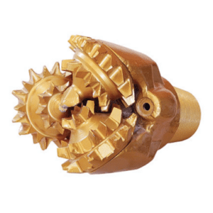
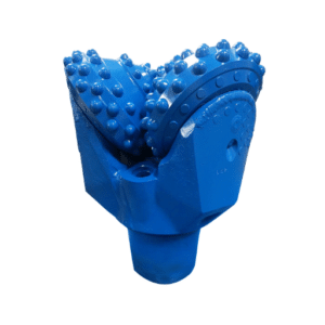
Usually, cobbles, boulders, or bedrock making it hard for the grab to bite or penetrate the soil forces contractors to utilize rotary drilling buckets fixed to Kelly bars. In this case, these buckets gather and remove all necessary material by a circular approach without any straight forward grab biting actions. Common types include:
- Soil buckets with flat cutting edges for cohesive soils and sand
- Rock buckets with bullet teeth or roller bits for fractured rock and boulders
- Cleaning buckets with tight bottom seals for removing sediment and loose debris before concreting
In practice, the rotary bucket usually serves to disturb the obstacle while the scoop in the form of a grab continues to cut off the refuse as before. The two mentioned systems are finding a lot of use in mixed soils where there are layers of rock interrupting other soils or materials which could be excavated.
Trench Cutters (Hydromills): When Grabs Reach Their Limit
In the case of consistent rock hardness or underwater drilling, however, the grab can be substituted entirely by a hydromill or a trench cutter. Hydromill is made by having two wheels, which are activated by a motor, placed at the bottom of the trench and they grind soil and rocks that they move on their way to the surface. The waste comes with the slurry and is taken to the surface for desanding with the help of the pump. Even in the most difficult conditions, the depth can exceed 250 meters.
A Hydromill is a device that can be compared to a drilling bucket in both form and function. During the course of the project, hydromills are used when the performance of the clamshell is not sufficient, which develops particularly well in rocks with unconfined compressive strength greater than 10 MP. In addition, the SPT N-values are usually more than 50 for rocks having such strength.
Key Factors in Selecting Slurry Wall Excavation Equipment

The complexity of this technology stems from that for the most efficient slurry wall process the identifier must be found among the four input variables: the soil type, the wall dimensions, the level of precision required, and the financial resources available.
Soil Conditions and Hard Strata
Soil type has a great influence on equipment selection. In easily dressable soils like soft clay, loose sand, alluvial, etc., mechanical grabs are a great help and economically beneficial. In clayey silt, partly because these machines are adequate for the job in this soil and are cost to use, hydraulic grabs are utilized. In other cases such as areas with boulders or in rocks that have oxidative effects, drill and grab will have to be used. In the extreme cases due to impossible drilling, the only alternative will be the hydromill.
The nature of soil also triggers the preferential choice of the technology. The soils with high quartz content cause much faster grab teeth wear. In such conditions it is also reasonable to use a hydraulic grab with replaceable teeth and shells strengthened.
Panel Depth and Width
The depth of excavation also entails the specialized activity as to reach it, backhoes, grabs or cutters will be necessary. Backhoes are suitable for excavation works from the ground level up to 20 meters below. For the larger excavation volumes, the clamshell grabs will start operating. Hydraulic grabs are designed to go much further, for pits of 250-600 feet in depth or even more. Hydromills are suitable at any depth, producing the world’s largest or thinnest walls.
Width has an effect on both equipment selection and the cost of materials. Cement and bentonite slurry walls can be more cost effective when the width is small, sometimes as small as 1.5ft. On another note, diaphragm walls including beams and planks, can range from 600mm to 1500 mm. The application of hydraulic grabs and hydromills results in the ability of narrow walling all the time. Mechanical grabs or draglines may at times necessitate wider excavations which increases the cost of slurry and backfill.
Verticality Requirements
Diaphragm walls of high standards require stringent and vertical tolerances, typically standing at a ratio of 1/300 or even better. For these capital intensive structures, there are situations which justify 1/1000. Additionally, the Kelly hydraulic grabs that are mounted on a leader system are outfitted with an inclination sensor, which shall enable the operator to ascertain any deviation or correct the same in the course of operation.
The latest hydraulic grabs have self-correcting systems. If the grab is inclined, the collar on the Kelly bar moves the bucket, cutting off the soil. But this is mainly applicable to hydraulic grabs, which hard to implement the same with the cabled type.
Project Scale and Economics
Backhoe and mechanical grab may be fit for carrying out minor containment wall works in soft material. Axial wall cities’ construction works however cannot be done without hydraulic grabs, which are more costly. With the vast volumes of rock exaction free-standing foundations occur in small holes, water mills become viable regardless of the high initial cost.
The most important cost factor is the cycle time. A more expensive 30% faster implement can actually pay for itself over the mileage of a long wall. A cheaper implement that makes fatigue soil hard to work on becomes more expensive due to greater overhead variables.
Want a custom equipment recommendation for your slurry wall project? Request a free technical consultation from the Changsha Mingyi engineering team.
Slurry Wall Construction Process Step-by-Step

Knowing the complete scenario of the work helps the contractors understand how best these equipment uses what kind of drills or grabs. The methodology invariably follows an approach that takes care of each wall type.
Step 1: Guide Wall Installation
The guide walls are initially constructed along the base of the wall line. These walls have a dual structural quality. They keep the base of the wall parallel to the wall line and brace the soil while enabling the cuts to go in without the soil falling in. These walls also serve as supports for the cages while the steel members are to be connected in place.
The usual depth of guide walls is 1.0 to 1.5 meters. This aligns with the depth of a panel. The positioning of the guide walls should be perfectly aligned with the marks made on the ground since this is the reference for the next operation to follow. Depending on the approximate dimensions of the walls, those panel demarcations may have different lengths but cannot be more than 8m in length.
Step 2: Panel Layout and Primary-Secondary Sequence
The total wall length is divided into discrete panels. Primary panels are excavated and poured first. Once the primary panels were cast and cured or the stop-end pipes were fully fitted, the excavation of secondary panels between them followed. The secondary panel is positioned in such a way that it partially camouflages both ends of the primary panel creating a sort of one-piece wall.
The length of the primary panel depends on soil condition and the available size of equipment and ranges between 4 and 8 meters. The fixed size of the excavated belt will leave smaller secondary panels that are in the voids filled.
Step 3: Slurry-Supported Excavation
This is where the grab does its work. The trench remains filled with a slurry most of the time, often with the slurry close to the ground level. The digger bit down on the soil, picked up its area of operation, and brought it up. The operator of the plant goes through the exact same steps as the procedure progresses in the course of the hole being made.
For a standard 6-meter panel, a common grab sequence is:
- Dig a single hole at one end
- Dig a single hole at the opposite end
- Excavate the middle partition between the two end holes
This “three-grab” sequence ensures full-width excavation and better verticality control.
In the event that solid rock is encountered, an auger grab is used as a contingency. The auger breaks the rock through the cutting action, and the grab is involved in stripping operations to the extent that such rocks are removed.
Step 4: Bottom Cleaning and Quality Control
When the excavation is done, the bottom of the trench must be clean before any concrete can be poured or any reinforcement can be placed. In case of quality work, the thickness of the sediment should be less than 50 mm. Contractors use four methods to clean the base:
- Pump suction
- Airlift reverse circulation
- Agitating submersible pumps
- Direct grab removal with a cleaning bucket
Besides, the wall cleaning should not be neglected. A wall brush or direct grab is run down the sides of the trench to scoop out any incriminating materials. Particular regions housing surfaces that abut others, are cleaned by rubbing the surfaces and dirt to fall at some point.
As part of the procedures to be followed during this period, slurry characteristics are tested. Slurry density, silt content, viscosity, acid resistance, sand grain size, yield value, and physical properties have some limitations. The amount of sand, however, should not be more than 5% due to risk of hard settling.
Step 5: Reinforcement and Concreting
In the case of a structural diaphragm wall, the prefabricated steel reinforcement cage is placed in the slurry filled trench in the vertical position and supported by the construction guide walls. Subsequently, concrete is poured from the last segment supported by a relatively lighter bottom discontinuity tube and jumping the rest of the slurry. The cleaning solution is then pumped out of the slurry trapping plant for recycling operation purposes.
Once the excavation is completed, for the construction of cut-off wall structures the excavation backfill comprises of the soil-bentonite slurry only or the cement-bentonite slurry is constructed and remains in place to harden.
Common Equipment Selection Mistakes

Even expert workers make wrong choices when it comes to the tools to use in slurry wall cutting. Below is a guide to the most common errors and explains how to move beyond them.
Using Mechanical Grabs in Hard Soil
One of the errors happens while selecting a grab type where a Hydraulic grab is recommended but the mechanical grab is preferred due to its low cost. In the case of dense clay or glacial till, the mechanical grab is observed to wear off the body. They cycle in and out so fast that it becomes difficult to steer them. What could have been gained in the form of cheaper rental costs for mechanical grabs is gone, as it is not generated with full efficiency as before.
Undersizing Bucket Width for Panel Overlap
Some claim they use a catcher that is equal to the length of the panel and not practical. They fail to understand the necessity of ‘overlap’ and the effect of the wall placement error. Stretching a grab wider than the design width can cut horizontal soil slices along the Designed Panel edges leaving a gap which can lead to a resultant failure of the joint between the primary and secondary panels.
Ignoring Slurry Properties and Sediment Buildup
Damaged grab shells with faulty seals allow slurry to leak through, and it is not possible to keep fine cuttings because of the leakage shall success. As a result, the amount of sediments in the slurry is more enhanced and settles at the bottom of the trench leaving the floors of the trench to be cleaned going up. Such situations can be dealt with through proper maintenance of the sealings and teeth ribs of the grab.
Skipping Verticality Monitoring
Conclusion
When employing the drilling buckets for slurry wall construction, many factors must be taken into consideration. Indeed, getting the right equipment is only part of the job. One needs to consider what kind of soil is present, how deep the concrete walls are, the width of the panels and whether the project is high end or low-budget or how the boreholes are to be constructed. Often, a mechanical grab that functions effectively in loose clays may be disadvantageous in stiff tills. Further, a hydraulic grabbing system designed for an urban diaphragm walling may sometimes be too much even for a shallow cutoff wall. Particularly in the presence of rock, another tool such as the professional drum cutter or hydromill is needed!
Here are the key takeaways:
- Start with the soil. Soil type determines whether a mechanical grab, hydraulic grab, or trench cutter is appropriate.
- Match depth to equipment. Backhoes for shallow work, grabs for deep panels, hydromills for extreme depths and hard rock.
- Control verticality. Kelly-guided hydraulic grabs with real-time monitoring are essential for tight-tolerance walls.
- Account for width economics. Narrow walls save material but require precise equipment.
- Keep slurry clean. Tool condition directly affects sediment control and panel quality.
Mingyi Machinery manufactures drilling buckets, slurry wall grabs and other types of foundation drilling tools which are quality and well suited for every soil condition and for every construction project. The combinations of each sleigh element are usually unique, and this leads to the risk of the necessity to construct the sledge in a different manner. We use the engineering design methods that can help in the development of these sledge types and therefore justify their construction and that also take into account the convenient usage of the sledge.
Contact us today for a free equipment assessment and custom tool recommendation based on your slurry wall project requirements.